
I am addicted to pinball. There is one pinball app for android, in particular, that I can’t stop playing. Unfortunately, playing on my Nexus 7 really cramps my thumbs. The solution? Well, make a game controller, of course!
Now, the downside to this particular game is that it does not support keyboard or joystick control options, so you are limited to touch events. Injecting touch events from one application to another is a no-no (there are obvious security issues associated with that). So, the only other option for creating a custom controller for this game is to emulate a mouse. Mouse clicks will register as touch events. The downside to this approach is that you can’t click your mouse in two places at once, which means you can’t have both flippers up at the same time… or can you? It turns out that if you are pressing on the left side of the screen (and hence the left flipper is up), then you can slide your finger to the right (which causes a release of the left flipper, and a press on the right), and then slide BACK to the left. When you do this last motion, both flippers will remain in the up position. Well, sometimes they both remain up. It’s actually a bit wonky, so I can only assume this is a bug and not a feature. However, we can definitely try to make that happen; it’s a simple matter of programming (SMOP). 😉
To get started, I figured a bluetooth mouse would be best. So, I sourced some parts:
-
(1) Bluetooth Modem – BlueSMiRF HID
-
(2) Arcade Buttons
-
(1) Arduino Uno
-
NTE 74LS00 Quad 2-input NAND Gate (sourced from a local electronics shop)
- (4) 10k 1/6W resistors
The arcade buttons are SPDT. Initially, I hooked them directly up to the microcontroller’s input pins, and boy did that cause a lot of confusion for my code! Needless to say, debouncing circuits are a must. To give you an idea of what the input looks like to the microcontroller without any debouncing circuitry in place, here is a screen grab from my logic analyzer during a button press:

Channels 1 and 2 are connected to NO and NC on the switch. Those transitions look pretty clean, right? Let’s take a closer look at the transition just after 1s:

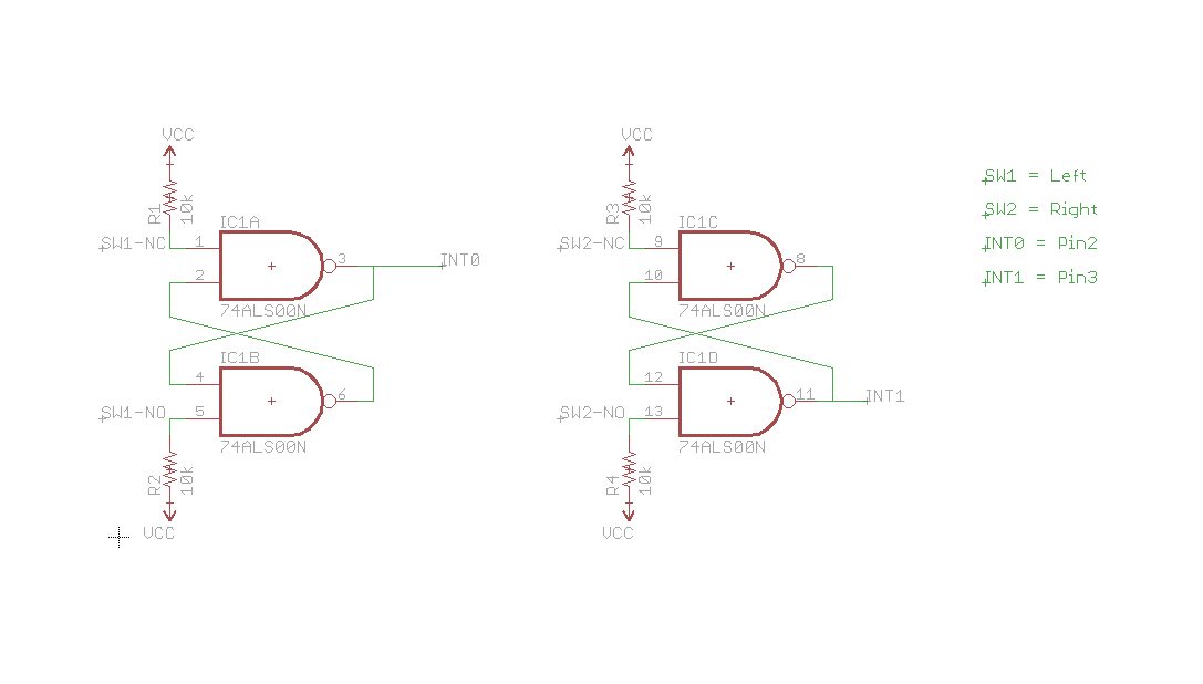
Notice how both channels are showing a logic 1 for almost 4 ms! Clearly we need to fix that. Luckily, I stumbled upon this web site, with a very comprehensive explanation of debouncing: http://www.ganssle.com/debouncing-pt2.htm. Following the advice on that page, I constructed an SR Latch using two NAND gates.

NAND SR Latch
The output from the first gate (Q) is wired to the input pin on the microcontroller. After putting this circuitry in place, I no longer saw any bouncing from the arcade buttons. Success! Here is a schematic for the NAND gate:
And here is what the circuit looks like when breadboarded:


The connections on the BlueSMiRF are pretty straight-forward. You have VCC, GND, RX-I, TX-O, RTS and CTS. I wired RTS directly to CTS, since the arduino doesn’t really support hardware flow control. RX-I goes to the arduino’s TX pin, and TX-O goes to the RX pin.
Next up, I had to configure the bluetooth modem. I chose to set it up as a mouse, and use raw packets to send position and button information to the host (my android tablet in this case). To set the device up, I had a rube goldberg-esque configuration of cables. Into the PC, I plugged a USB to serial adapter. From there, I have a Sparkfun serial breakout board (which shifts levels down from the serial port, but not back up from ttl). I connected the output from that into the BlueSMiRF breakout board (which is very tolerant of voltages, by the way). With all that in place, I was able to send serial commands from minicom (a serial communication program) to configure the radio.
The RN-42 (bluetooth module) supports 4 different authentication modes:
- open mode (no pin required)
- keyboard I/O mode (a verification code is displayed on the host, which should match the code displayed on the device)
- Secure Simple Pairing (SSP), or just works mode
- PIN code mode
Since android was specifically called out in the documentation for keyboard I/O mode, I tried that first. It worked, but only the first time connecting to the device. Subsequent attempts to connect simply didn’t work. Clicking on the device name in the bluetooth settings on the tablet did not do anything. Literally, there was no feedback, no error message, no evidence that I had ever even pushed the button. I tried changing the HID profile of the device and changing the authentication mode to no avail. So, I hooked up adb and checked the logs:
D/CachedBluetoothDevice( 4359): Command sent successfully:CONNECT Address:00:06:66:4B:3D:D2 Profile:HID
W/bt-btif (  984): btif_hh_connect: Device 00:06:66:4B:3D:D2 already added, attr_mask = 0x8075
E/bt-btif (  984): btif_hh_connect: Error, device 00:06:66:4B:3D:D2 can only be reconnected from device side
W/HidService(  984): no state change: 0
How is that for a cryptic message? It comes from here in the sources, in the off chance that someone happens to be interested. I did not wish to dig into the problem any further at that very moment, so I scrounged through all of my android devices until I found one that worked: the galaxy tab 10.1.
For the enclosure, I wanted it to be roughly the same size as the front-end of a pinball cabinet. The most crucial dimension is the width, which comes in at either 22 or 24″, depending on the machine. I decided to give 24″ a try. The depth of the enclosure has to be large enough to accommodate the hardware, and the height must be such that it can fit the buttons. I settled on a front height of about 4″ and a depth of 8″. Because this is just a prototype to test the size for comfort, I did a real hack job on the enclosure, using whatever scraps I had lying around. It isn’t pretty, but it gets the job done. And, in fact, it is actually comfortable to use
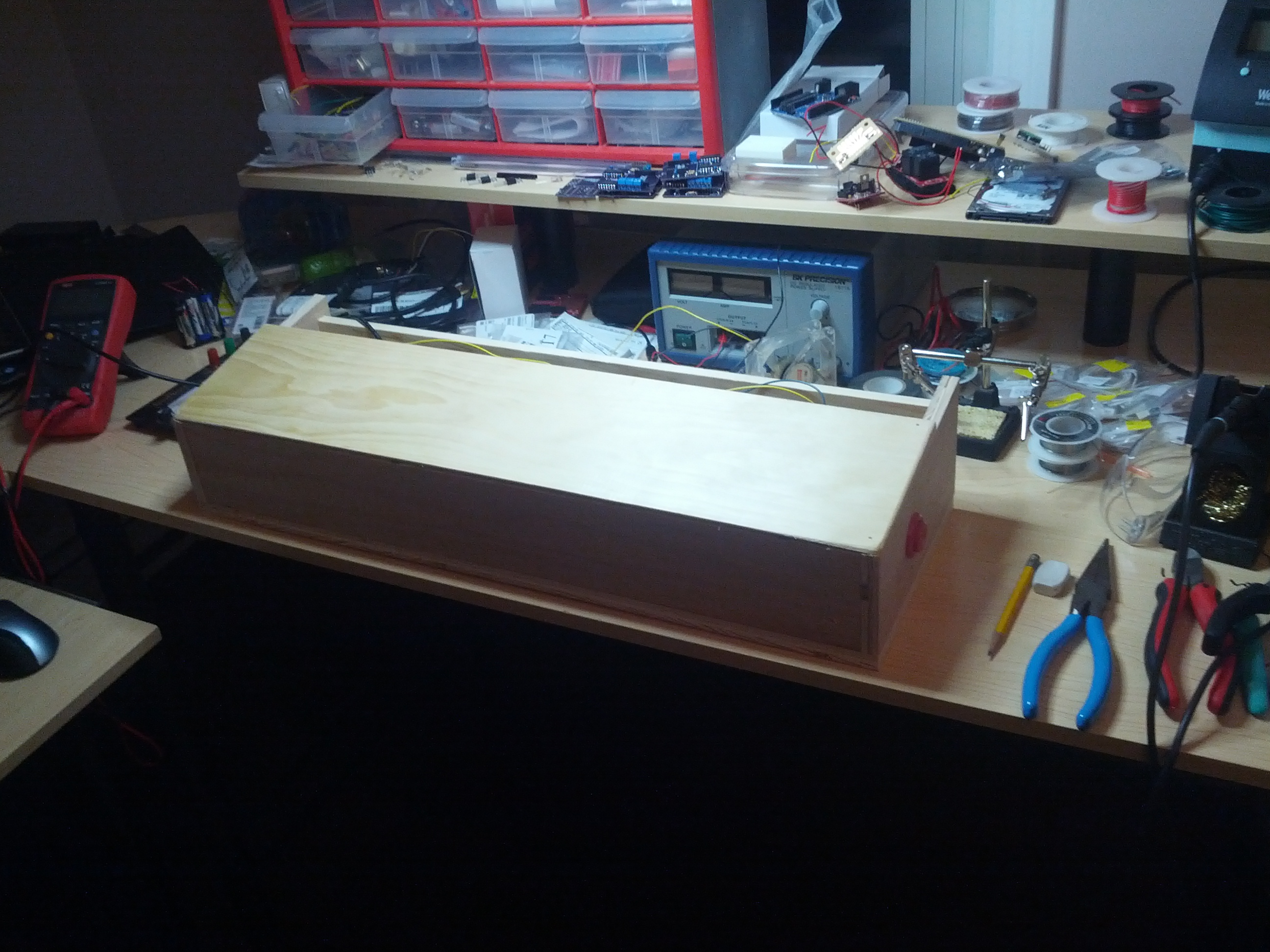 I left an opening in the back to get components in and out. Here you see the arduino and breadboard stuffed in there.

Now, on to the code. I didn’t want to implement a polling mode driver, as it is too easy to miss events, and the code isn’t quite as clean. Instead, I wired the outputs from the SR latches to pins 2 and 3 on my Arduino Uno, which are the external interrupt pins. Any change (press or release) on these pins will trigger an interrupt, and the registered interrupt service routine (ISR) will be called. In the ISR, I simply add the event to a ring buffer, and increment a counter indicating there is work to do in non-interrupt context. Then, inside the loop() function, I check this counter and, if it is non-zero, pull an event off of the ring for processing. In this way, we can ensure that events are processed in the order in which they were received. And given how little code executes in interrupt context, we can be fairly certain that we won’t miss events. One thing to be careful of, though, is disabling interrupts when checking any variable that will be accessed by the ISR.
The prototype works, and is actually very usable. There is some lag, which I’ve grown used to, but new users seem to have a harder time with it. Naturally, I’d like that to go away, so I decided to see where that lag was coming from. In order to track it down, I decided to hook the logic analyzer up to several points in my circuit. First, the NC and NO switch connections, along with the Q output from the SR latch. This will tell how long it takes for a button press to be debounced. Then, I also wanted to see how long it would take to propagate the button press to the bluetooth modem, essentially measuring the overhead of my code. So, I put a probe on the RX pin on the BlueSMiRF breakout board. I also wired up TX, but that proved uninteresting, as the board never sends any serial data back to the microcontroller. This covers everything that I have direct control over. The result of a button press looks like this:

As you can see, I attached an “Async Serial” protocol analyzer to the “RX” channel, which I used to verify that the expected series of bytes is sent to the module. More importantly, though, we can see that it takes 2ms for the button press to make its way through the SR latch (the delay between NO going high and Q going high). After that, it takes a little under 40μs to start sending data to the bluetooth module. After another 1.1ms, the two packets have been sent to the modem, making for a total time of around 3ms for a button press event to be sent to the bluetooth modem. Based on this data, I think I can safely rule out my circuit and code as the source of the lag.
Given that I have no control over the lag (without digging into the bluetooth stack on my tablet, that is), and given that android support for the RN-42-HID seems so spotty, I think the next obvious step would be to implement the controller as a USB HID device. It turns out you can flash the arduino with USB HID firmware, discussed here. That means that the android device will have to support USB host mode, but that’s not a problem for most of the devices I own.
I just received a ball shooter assembly, and it looks like it will fit into the prototype cabinet!

My next update will hopefully see that installed and working. I think I’ll use an IR distance sensor to determine how far the plunger is pulled out, and translate those offsets to mouse click and drag events.
The source code can be found here. Leave a comment if there’s anything I didn’t cover here that you’d like to know (more) about.
Finally, here is the obligatory demo video:
